
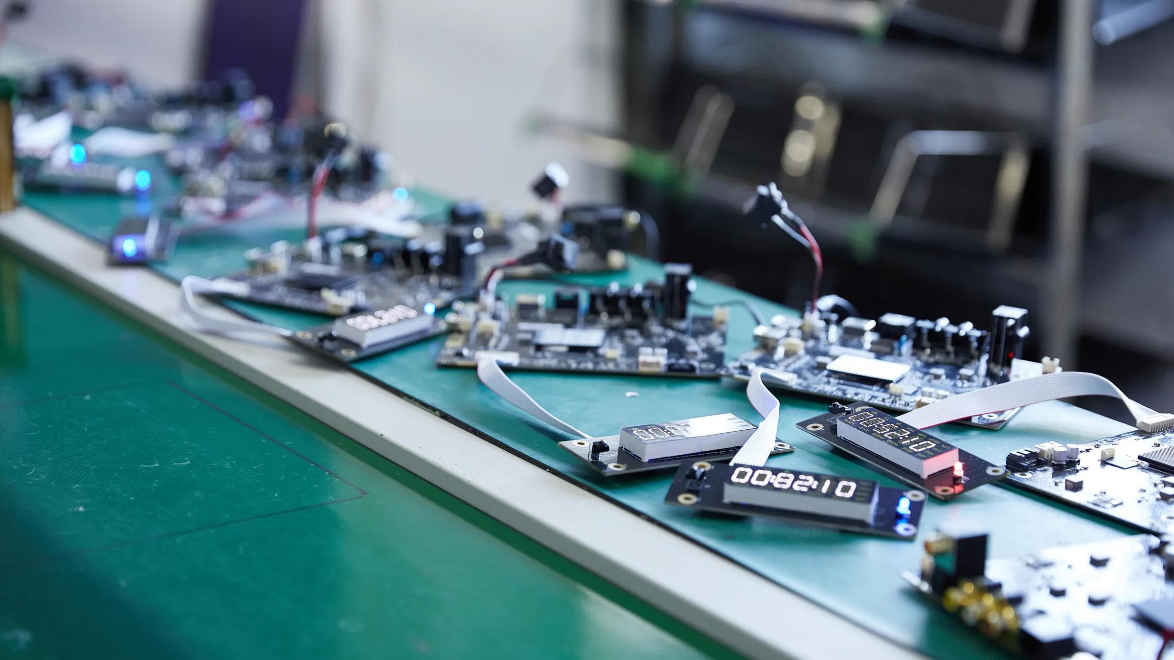
AI data centers are no longer only computing projects. They are increasingly power-and-cooling projects in which every additional rack changes the electrical load, the thermal load, and the control problem at the same time. For control electronics, that means the PCB assembly must be evaluated against the system it will manage—not only against a schematic and a bill of materials.
This is the practical shift: a control board for an AI-ready power or cooling system needs clear operating boundaries, stable interfaces, and a test plan that reflects real electrical and thermal conditions. At Venture Electronics, we treat those system inputs as part of the manufacturing conversation because they influence component choices, layout constraints, connectors, assembly details, firmware handling, and verification.
More computing power becomes more heat to manage
The International Energy Agency's 2025 Energy and AI report describes the growing relationship between AI, data centers, and electricity demand. At facility level, the engineering consequence is straightforward: almost all electricity entering computing equipment ultimately becomes heat. Lawrence Berkeley National Laboratory makes the same relationship explicit in its 2026 work on AI infrastructure thermal integration.
That does not mean every control board suddenly becomes a high-power board. It means the board is operating inside a system with tighter coordination requirements. Power distribution equipment, pumps, fans, valves, sensors, leak detection, alarms, and supervisory controls may need to react to changing workloads and thermal conditions. A board that performs correctly in a quiet bench test can still be unsuitable if its interfaces, thermal assumptions, or protection logic do not match the equipment around it.
The control board is the coordination layer
A useful way to understand the role of control electronics is as a four-part loop: sense, decide, act, and verify. Sensors report temperature, pressure, flow, voltage, current, and equipment status. The controller interprets those signals. Outputs command fans, pumps, relays, contactors, valves, or power modules. Communications report status upward and receive new setpoints. The system then checks whether the requested action produced the expected result.
Each link in that loop becomes a design and manufacturing input. Sensor types define signal-conditioning needs. Communication protocols define transceivers, isolation, connectors, and firmware interfaces. Actuator loads influence output-stage design and protection. Sampling rates, fault thresholds, and response timing influence both hardware and software validation. Venture Electronics therefore looks for the relationship between the PCB assembly and the controlled equipment, not merely a list of components.
System pressure becomes board-level requirements
Power and cooling constraints usually reach the control PCB assembly through several routes. Higher currents can affect copper paths, connector ratings, terminal choices, and local heating. Dense enclosures can change airflow and component temperature. Liquid-cooling equipment can add pump, valve, flow, pressure, and leak-detection interfaces. More distributed equipment can increase communication ports and create new grounding, isolation, and electromagnetic-compatibility questions.
Mechanical conditions matter too. Connector orientation, cable bend radius, mounting points, component height, service access, and proximity to hot components can determine whether the finished assembly works in the enclosure. These are not details that an assembly supplier can safely infer from Gerber data. They need to be stated, reviewed, or confirmed.
A stronger RFQ starts with operating boundaries
A conventional PCB assembly request may begin with Gerber or ODB++ files, a bill of materials (BOM), component placement data, and an assembly drawing. For a control board serving power or thermal equipment, that package becomes more useful when it also defines:
- input voltage, load ranges, power rails, and protection expectations;
- ambient and local temperature conditions, airflow, and known heat sources;
- sensor, actuator, connector, and communication interfaces;
- firmware version, programming method, and configuration rules;
- mechanical constraints, enclosure interfaces, and assembly sequence;
- test conditions, pass/fail criteria, records, and acceptance responsibility;
- prototype quantity, production quantity, version status, and change-control process.
The objective is not to make the RFQ longer. It is to give engineering, sourcing, and manufacturing teams the same definition of the product. A complete, version-aligned package lets Venture Electronics assess PCB Assembly, BOM Review, DFM/DFA questions, programming, and testing as one connected project.
Testing must move beyond continuity
No single inspection method answers every quality question. Solder paste inspection can identify paste-related issues before reflow. Automated optical inspection can check visible placement and solder features. X-ray can help inspect hidden joints where the structure justifies it. In-circuit testing can examine selected electrical conditions, while functional testing checks whether the assembled board behaves as intended under a defined setup.
For data-center control electronics, the important phrase is under a defined setup. A functional test needs the correct firmware, loads or simulators, communication conditions, test steps, limits, and result format. If temperature, flow, voltage, or fault inputs matter to the product, the test plan should state how those signals are represented and what response counts as a pass. Venture Electronics can discuss an inspection and test combination from the project files, but the required coverage depends on the board structure and the customer's system-level verification plan.
Design the manufacturing handoff as part of the system
AI infrastructure will keep drawing attention to processors, accelerators, and network equipment. Yet usable computing capacity also depends on the electrical and thermal systems that keep those assets powered, cooled, monitored, and protected. Control electronics sit at the point where those systems exchange signals and actions.
The best time to make that control layer manufacturable is before files are released for production. Share the operating boundaries, interface definitions, mechanical constraints, controlled BOM, firmware, and test intent together. Venture Electronics can then turn the review into concrete questions, confirmation items, and a project-specific PCB Assembly and testing scope.
Consider an RFQ for a cooling-control board that receives temperature, flow, pressure, and alarm inputs and sends commands to pumps or fans. The manufacturing package should not attempt to reproduce the whole data-center cooling plant. It should identify which signals reach the board, their electrical ranges, how abnormal inputs are simulated, which firmware version interprets them, and what outputs or messages constitute a pass. Mechanical drawings, connector definitions, load fixtures, communication setup, and result records then become part of the same handoff. This gives the customer ownership of system-level behavior while giving Venture Electronics a defined basis for BOM Review, DFM/DFA, programming, fixture discussion, PCB Assembly, and selected board-level testing. The boundary is practical: facility conditions become explicit test inputs, but system commissioning remains a separate activity.
For teams building the next generation of AI power or cooling equipment: which system condition is hardest to represent in your current control-board test plan?